Optical Path Calculations
This page calculates the performance of a basic optical communications link using a simple LED and photodiode with no optics between them. A diagram of a simple optical link is provided below. Demonstrations are provided showing how to extract parameters from a typical LED datasheet and convert them into the values needed to characterize the performance of a free space optical link.
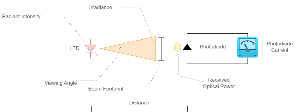
Page Organization
This page is organized into the following sections:
- Overview of the basic units used in optical path calculations
- Converting from luminous intensity to radiant intensity
- Converting an LED viewing angle into solid angle (steradians)
- Calculating total radiant flux emitted (within viewing angle)
- Calculating irradiance at a given distance from the LED
- Calculating the expanding beam footprint at a given distance
- Calculating the received optical power at a given distance
- Calculating the photodiode current produced at a given distance
The following constraints and assumptions apply to the calculations on this page:
- The use of optical lenses are not in the scope of this page
- Received power and irradiance assume the receiver area is well within the beam footprint
- The light hitting the photodiode is perpendicular to the surface
The Units of Light
This section introduces the basic units used to describe light emitted over a free-space path, with focus given to those commonly found in LED datasheets.
Solid Angle - The Steradian (, sr)
Both luminous intensity (cd, or lm/sr) and radiant intensity (mW/sr) are defined as power per solid angle, so it is important to understand this concept first.
The solid angle, measured in steradians (sr) and denoted by , is the area (A) on a sphere subtended (cut out) by a cone with its apex at the sphere’s center.
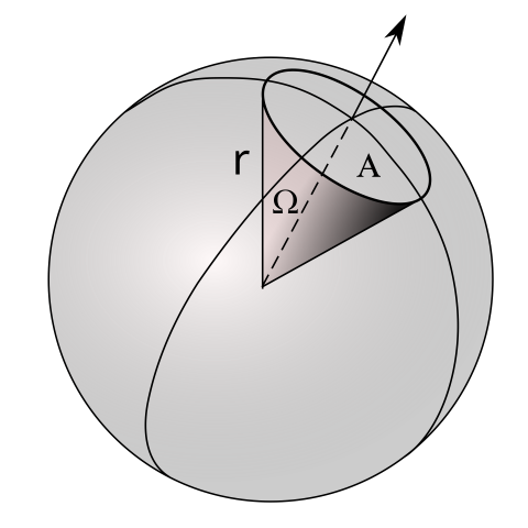
A solid angle, , is defined by the surface area of a sphere:
A steradian is the unit of solid angle that subtends an area equal to on the surface of a sphere. Since the solid angle is defined as , and the surface area of a sphere is , the radius dependence is removed, leaving a normalized result expressed in steradians.
| Steradian | Conversion Parameter |
|---|---|
| Complete sphere | |
| Hemisphere | |
| A patch of area of the sphere |
The solid angle can also be calculated using the half-angle from the center of the sphere by substituting the formula for the surface area of a spherical cap
into
this cancels out the terms. This allows the solid angle to be calculated using only the angle of the cone projected from the center of the sphere. By the definition of the surface area of a spherical cap, the half-angle (center axis to outer boundary) is used.
where is the half-angle. If the full-angle (boundary to boundary) is used, you must divide the full-angle by 2.
Luminous Intensity
Luminous intensity is a photometric unit that describes the perceived power of a light source, weighted according to the sensitivity of human vision. It is defined in candela, , which is also equal to lumens per steradian .
This is the optical power parameter most commonly listed in visible-wavelength LED datasheets, since most visible-wavelength LEDs are designed for visual indication. A wavelength-weighted chart for luminous intensity can be found at the HyperPhysics website.
Radiant Intensity
Radiant intensity describes the optical power emitted by a source per unit solid angle. As a radiometric unit, it represents a physical measurement of optical power without any wavelength-weighted conversion.
Radiant intensity is defined at the source, such as the emitter within an LED, for a given solid angle. Radiant intensity is used to calculate irradiance which is the power density at a given distance from the source as it spreads out along the respective spherical surface area.
Converting Luminous Intensity to Radiant Intensity
To convert luminous intensity into radiant intensity (or vice versa), use the luminous efficiency conversion factor K. This is defined as:
where
- = Luminous Intensity
- = Radiant Intensity
- = Photopic Luminous efficiency.
The Photopic Luminous efficiency is a dimensionless value that is found in a lookup table such as that provided by HyperPhysics.com. This website also lists the computed conversion factor (K) for a given wavelength, which is based on the normalized 555nm wavelength at 683 lm/W under the “Photopic Conversion lm/W” column.
Example Calculation
The following example demonstrates how to convert luminous intensity found in a typical visible-wavelength LED datasheet to radiant intensity. Two primary conversions are required, as summarized below.
| Datasheet Parameter | Needed Parameter | Conversion Description |
|---|---|---|
| Luminous Intensity ( | Radiant Intensity () | Convert the photometric quantity into a radiometric quantity |
| Viewing Angle () | Steradian () | Viewing angle is the full angular width of the cone of light where light intensity has dropped by 50%. Note: Datasheets typically specify a full angle , whereas the steradian formula below requires the half-angle . |
The LED used in this example is the Broadcom Limited: HLMP-EG1A-Z10DD.
| Parameter | Value | Source |
|---|---|---|
| Dominant Wavelength | 626 nm | Datasheet overview |
| Viewing Angle | 15 | Datasheet overview |
| Luminous Intensity (mcd @ 20mA) - Min | 12000 mcd | Basic Characteristics Table |
| Luminous Intensity (mcd @ 20mA) - Max | 21000 mcd | Basic Characteristics Table |
| Luminous Intensity (mcd @ 20mA) - Nominal (interpolated) | 16500 mcd | Interpolated from Min/Max values |
Note: 1 is equal to
Referencing the HyperPhysics website table, which is listed in 10nm increments, interpolate between 620 nm () and 630 nm () to estimate (). For the purposes of this example, 625 nm is close enough to 626 nm; use the conversion factor for this wavelength going forward.
The conversion factor is therefore:
The final radiant intensity conversion is:
Converting Viewing Angle Into Solid Angle
As discussed earlier, the viewing angle can be converted into steradians using:
Where:
- The light source’s 50% intensity half-angle
Example Calculation
Convert the Viewing Angle from degrees to radians
Total Radiant Flux
Having computed both the radiant intensity and the solid angle of the LED’s beam, the next step is to determine the total radiant flux emitted within the viewing angle. Total radiant flux is the total optical power () emitted within the viewing angle.
This is particularly useful if collimating lenses will be added to the optical path in the future.
Example Calculation
Calculate the expected optical power being emitted from the example LED within its viewing angle.
Although is emitted from the LED within the angular spread of the beam, only a small fraction of this power will land on the photodiode to be converted into an electric current.
Irradiance at Distance
With the radiant intensity now determined, the next step is to calculate the power spread across the surface of the expanding spherical cap at distance from the LED. Irradiance is the radiometric unit describing the radiant flux (energy per unit time) over a defined surface area. Although the radiant intensity is independent of the distance from the source, the surface area over which the power is distributed grows with distance, reducing the irradiance . This relationship follows the inverse square law. Knowing the irradiance at a given distance is a key step toward determining the optical power received over a photodiode’s active area.
Irradiance is calculated using the formula below source. This equation assumes the detector area is much smaller than the beam footprint, otherwise integration would be required.
where
- Irradiance
- radiant intensity ()
- angle (radian) between the surface normal and source light
- distance from the source ()
If the light hitting the surface is perpendicular, and the irradiance equation becomes:
Example Calculation
The following table shows the irradiance at two distances from the example LED used in the previous conversion step. This example assumes the LED is directly pointed at the detector, .
| Distance | Radiant Intensity | Irradiance |
|---|---|---|
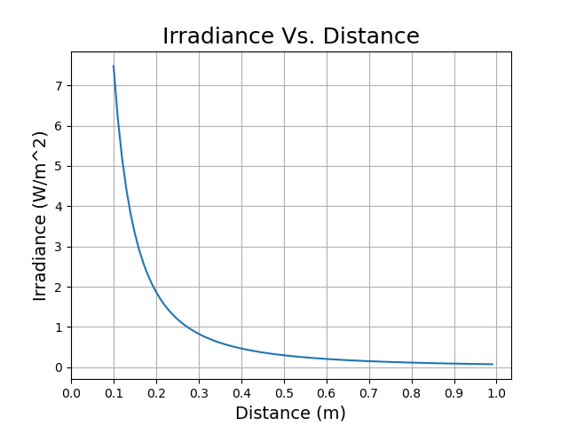
| 10 | 74.8 | 7.48 |
| 20 | 74.8 | 1.87 |
The plotting of Irradiance vs. Distance below demonstrates the inverse square law in action.
Beam Footprint
The beam footprint diameter can be calculated from the LED’s viewing angle. Note that the viewing angle defines the full angle at which the intensity has dropped to 50% of its peak, light will extend beyond this calculated footprint.
Where:
- The beam footprint diameter
- The distance in meters from the source
- The LED viewing full-angle
Example Calculation
Calculating the 10 cm and 20 cm distance footprints shows the growth of the footprint as distance is increased.
| Distance | Viewing Angle | Beam Footprint |
|---|---|---|
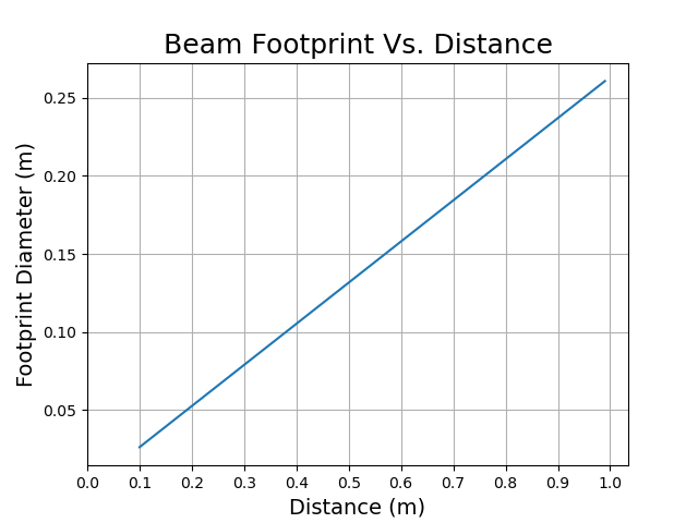
| 10 | 2.63 | |
| 20 | 5.27 |
Plotting the footprint diameter vs. distance shows the intuitive linear relationship (expanding cone).
Received Optical Power
The following parameters have been determined so far:
- Identified the luminous intensity of the example LED
- Converted luminous intensity to radiant intensity
- Calculated the irradiance at a given distance from the LED
- Assuming this area in question is completely within the subtended spherical cap of the solid angle
All of the information needed to calculate the received optical power for the chosen detector area at distance from the LED is now known. Since irradiance is defined by , the total optical power over a given area is found by multiplying the irradiance by that area.
The photodiode used in this example is:
Photodiode: Vishay: BPW34
| Parameter | Value | Source |
|---|---|---|
| Detector Area | 7.5 | First page overview |
| Reverse Light Current | 50 at 950 nm with irradiance 1 | Basic Characteristics Table |
| Relative Spectral Sensitivity S(626 nm) | Approx. 0.575 | Relative to the normalized peak sensitivity at 900nm and measured test current at 950 nm, Figure 7 |
Example Calculation
Photodiode Responsivity
First, convert the datasheet test irradiance from to :
And then convert the photodiode active area from to
Using the datasheet Irradiance and active area, compute the optical power received:
Then calculate the absolute responsivity at 950 nm using the datasheet test current at the stated optical power received at the photodiode:
Then calculate the actual responsivity at 626 nm:
Calculate Received Optical Power
The key parameters calculated thus far for describing the LED and photodiode optical path setup are shown below.
| Parameter | Value | Note(s) |
|---|---|---|
| 1.87 | Irradiance at the photodiode at | |
| BPW34 photodiode active area |
To calculate the optical power at the active area of the photodiode, multiply the irradiance by the active area of the photodiode.
Photodiode Current
To calculate the photodiode current for the LED and photodiode pair at a distance of 20 cm, multiply the received optical power by the photodiode’s responsivity at the LED’s dominant emitted wavelength.
Example Calculation
| Parameter | Value | Note(s) |
|---|---|---|
| 0.384 | Responsivity of the photodiode |
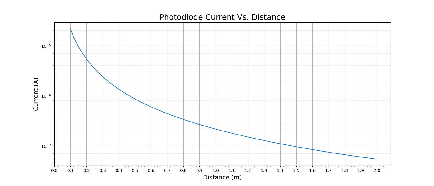
The expected photodiode current is plotted on a logarithmic scale to better show the large dynamic range over 2 m distance.
Conclusion
This page has demonstrated how to extract key parameters from typical LED and photodiode datasheets and calculate all of the metrics required to characterize a simple optical link. A natural follow-up will be to design and build this link and measure its actual performance.
Summary of Units & Variables
This section summarizes all of the units and variables used in this page for reference.
Units
| Unit | Symbol | Description |
|---|---|---|
| Steradian | Solid angle | |
| Candela | Luminous intensity () | |
| Watt per steradian | Radiant intensity | |
| Lumen per Watt | Luminous efficiency | |
| Nanometer | Wavelength | |
| Watt | Radiant flux / Optical power | |
| Watt per square meter | Irradiance | |
| Meter | Distance / Radius | |
| Radian | Angle | |
| Degree | , | Angle |
| Ampere per Watt | Responsivity | |
| Ampere | Electric current | |
| Square millimeter | Area | |
| Square centimeter | Area |
Variables
| Variable | Description |
|---|---|
| Solid Angle | |
| , | Area (Sphere patch / Photodiode active area) |
| Radius | |
| Half-angle / Angle between surface normal and source | |
| Full-angle / LED Viewing Angle | |
| Luminous Intensity | |
| Radiant Intensity | |
| Luminous efficiency conversion factor | |
| Photopic Luminous efficiency | |
| Wavelength | |
| / | Total Radiant Flux / Optical Power |
| Received Optical Power at Photodiode | |
| , | Irradiance |
| Distance from source | |
| Beam footprint diameter | |
| Responsivity | |
| Photodiode current | |
| Relative Spectral Sensitivity |